 Kia Sedona: ETC (Electronic Throttle Control) System Schematic Diagrams
Third generation YP (2014-2026) / Kia Sedona YP Service Manual / Engine Control / Fuel System / Engine Control System / ETC (Electronic Throttle Control) System Schematic Diagrams
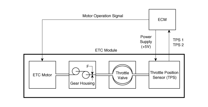
| Schematic Diagram |
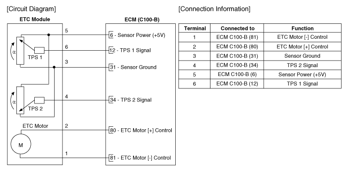
| Circuit Diagram |
 ETC (Electronic Throttle Control) System Description and Operation
Description
The Electronic Throttle Control (ETC) System consists of a
throttle body with an integrated control motor and throttle position
sensor (TPS). Instead of the traditional throttle cab ...
 ETC (Electronic Throttle Control) System Repair procedures
Inspection
Throttle Position Sensor (TPS)
1.
Connect the GDS on the Data Link Connector (DLC).
2.
Start the engine and measure the output voltage of TPS 1 and 2 at C.T. and W.O.T.
Throttle ...
Other Information:
Front Seat Shield Inner Cover Repair procedures
Replacement
•
When prying with a flat-tip screwdriver, wrap it with
protective tape, and apply protective tape around the related parts, to
prevent damage. ...
Components and Components Location
Component Location
1. Memory power seat unit (PSM)2. IMS control switch3. Outside mirror
...
Categories
- Home
- First Generation
- Second Generation
- Third generation
- Kia Sedona YP 2014-2026 Owners Manual
- Kia Sedona YP 2014-2026 Service Manual

Copyright © www.kisedona.com 2016-2026