 Kia Sedona: Auto Head lamp leveling Unit Description and Operation
Third generation YP (2014-2025) / Kia Sedona YP Service Manual / Body Electrical System / Head lamp leveling Device / Auto Head lamp leveling Unit Description and Operation
| Description |
According to driving environment and loading state of
vehicle, head lamp lighting direction is changed to keep the driver''s
visibility range and to protect the driver''s vision from glare, aiming
at safety driving.
Sensor integrated into ECU mounted on the rear center arm
drives the actuator mounted on the head lamp by sensing the input signal
in case of vehicle static change.
Head lamp beam is automatically operated by chassis tilt.
| Operation |
Operating Procedure
| 1. |
Suspension angle changes due to change in vehicle load. |
| 2. |
Sensor angle changes. |
| 3. |
Microprocessor calculates required degrees of change in head lamp angle. |
| 4. |
Sends a proper signal to head lamp leveling device and driving actuator |
Operating Condition
| 1. |
Ignition on |
| 2. |
Low beam on |
| 3. |
On stop : If sensor lever change is 0.3° and above, head lamp is operated after max. 1.5 sec |
| 4. |
On driving : If vehicle velocity is over 4km/h (2.48mile/h),
velocity change is not over 0.8-1.6km/h (0.5 ~ 1.0mile/h) per second,
and loading condition is changed, then head lamp is operated. |
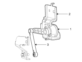
Components
| 1. |
Auto head lamp leveling unit
1. Leveling unit & sensor
2. Sensor mounting bracket
3. Sensor linkage
|
 Auto Head lamp leveling Unit Schematic Diagrams
Circuit Diagram
...
 Auto Head lamp leveling Unit Repair procedures
Inspection
1.
Ignition "ON".
2.
Turn on the head lamp switch.
3.
Check for operation. If the aim of the head lamps changes smoothly when the head lamp leveling switch is turned.
4.
If ...
Other Information:
Troubleshooting
Troubleshooting
•
The battery must be in good condition and fully charged for this troubleshooting.
...
24,000 km (15,000 miles) or 12 months
❑ Rotate tire
❑ Inspect battery condition
❑ Inspect air cleaner filter
❑ Inspect vacuum hose
❑ Inspect air conditioning refrigerant
❑ Inspect brake hoses ...
Categories
- Home
- First Generation
- Second Generation
- Third generation
- Kia Sedona YP 2014-2025 Owners Manual
- Kia Sedona YP 2014-2025 Service Manual
Copyright © www.kisedona.com 2016-2025

